(Last Mod: 04 November 2010 18:12:19 )
NOTE: WORK VERY MUCH IN PROGRESS
Links to other DragonWins pages
Links to external sites
Jonathan Westhues' Website (the inventor of the ProxMarkIII)
ProxMark III Developer's Community
ProxMark3.com (source for prebuilt boards and antennas)
Downloaded from Jonathan Westhues' website (24 JAN 10):
ZIP file with schematics, bill of materials, software, documentation
Bill of Materials (note - this has a couple of errors and out-of-date info that is corrected on the locally updated version)
ZIP file with board artwork
ZIP file with Eagle project files
Minimal File Sets for the PM3 (the Source Code is available from the ProxMark Community)
Jonathan WestHues' release
20090721_r52 release - version shipped by
ProxMark3.com as of Feb 2010.
Each of the zip files above contains the WinXP
executable (prox.exe), a batch file (prox-gui.bat) that will allow you to
launch it from an Explorer window, the three s19 files for the separate
firmware image areas, and a binary file (proximage.bin) that contains the
complete ARM Flash image.
The so-called "Open Source Community" is somewhat of a catch-all term (though there are specific licenses and legalisms involved) for projects in which all of the information needed to construct a project is made available openly and freely to anyone that wants it. The degree to which this is true is somewhat variable when a project includes hardware as well as software; a project is generally considered Open Source if the source code for any programs is made available even if the hardware designs are not. The situation with hardware is less clear cut. For instance, if the circuit schematics are made available, then many people will consider the hardware to be Open Source, even if the PCB (printed circuit board) layout is not made available. The reasoning is that someone with the schematics has all the information they need to lay out their own boards, if that is their desire. However, for some projects, the PCB layout is critical to circuit performance and may have taken the designer a long time to get right. Of course, the same is true for the software. So others argue that it can't truly be Open Source unless all of that information is made freely available.
The ideal of the Open Source Community is that a project, particularly software, that is made available to everyone in an open fashion will have relatively few errors in it because lots of people have the opportunity to look over the code and identify and correct bugs that are encountered. Also, by letting anyone that wants a new feature have the opportunity to implement it and feed that back to the project, it is believed that the project will evolve much faster and much more along the lines that users want than would be the case with typical closed source software.
If this is your first exposure to the Open Source Community, then there are some things you need to be aware of. First, the vast majority of people in this community are volunteers and are involved for the same reason you are: either to get something working without spending lots and lots of money or to get something working that isn't available commercially. It is a very loose knit community and it is unreasonable to expect too much from them. They are not there to provide product support, nor to provide a product of any kind at all. Accept that any help they give you is more help than you have any right to demand. Also accept that any help you get is going to be of highly variable quality - many of them are not a whole lot further along than you are and many of the ones that have the knowledge you need are so far along that they tend to forget that not everyone else is as familiar with the project as they are.
Also, don't expect high-quality documentation. Many people will agree that developing decent documentation is the greatest shortcoming of the Open Source community: there are no people being paid to produce it; developers generally like developing much more than documenting what they develop; developers are frequently very poor writers; different pieces of the documentation are written by different people with very different styles and very little coordination; and the projects generally evolve much faster then commercial products and hence documentation is always falling further out-of-date.
The ProxMark Community is no different. If anything, they are on the more frustrating end of the scale for the simple reason that the ProxMark Community is small. With only a few active developers, the pool of people to communicate with is less likely to contain the person that can answer your question in a way that you can understand. There are also fewer people to contribute to the documentation, both to improve it and just to keep it up to date. Plus, with only a few developers, they have not had to deal with the organizational and coordination issues that large Open Source projects have had to come to grips with. As a result, people make changes and commit them to the database without them being very well vetted and there doesn't seem to be a very organized concept of "last stable release" which larger projects put so much emphasis on. Nor does there seem to be a good mechanism in place to make sure that all of the changes (that are valuable) actually survive and get kept as the project moves forward; again, this is an issue that larger projects have been forced to deal with.
These things should be taken into consideration before you choose to use a product that relies on the Open Source Community. If you need something that is going to work out of the box and where you will know that you can get support if it is needed, especially if you have tight time constraints, then this is very likely not the path you should take.
The information needed to physically construct a ProxMark3 board is pretty straightforward and available from either Jonathan Westhues' website or the ProxMark Community website. If you have never worked with Gerber files or had printed circuit boards (PCB) manufactured, then you will probably be a bit lost. If that is the case, I would recommend contacting a PCB house, such as Advanced Circuits, and explain to them that you are new to PCB fabrication and that you are trying to get a credit card size 4-layer board manufactured and that you have the Gerber Files. They will probably be willing to walk you through the process. Expect to end up paying something on the order of $100 for a single board and be aware that you can probably get quite a few more boards for only a slight increase in cost (which may or may not do you any good).
Keep in mind that I am new to the PM3 and have never worked with an ARM microcontroller before. I do have a fair amount of experience working with Xilinx FPGAs and configuring them via JTAG, but have not used JTAG for much else. Essentially, I am maintaining a diary of what I am seeing and doing. In many places, I am going to have to assume that what I see is the expected behavior. Working for me in this regard is that I have constructed three PM3 boards and so if all three behave the same way, then there is a good chance that it is the correct behavior. Yes, I could have made the same error on all three, but the point is that it is unlikely that a solder bridge or bad solder joint or other simple mistake would result in all three boards behaving identically. Rest assured, if I find out that something I put here is incorrect, I will try to revise it with the correct information.
So let's get started.
Assuming that you have a newly built and untested PM3 in front of you, the first thing to do is see if it shows any signs of life. Do this by connecting it to a USB port via its mini-USB connector. Since the parts are not configured to talk to the USB, you will probably get a warning that the newly found USB device is not recognized and may not work properly. No surprise there. What should happen is that all three LEDs that are in a row "below" the large capacitor (red, yellow, green) should light as well as the single LED that is to the "right" of that same cap. If this isn't what you see, then something is wrong. It could be nothing more than an LED that is installed backwards or it could be serious problems. In either case, they should be tracked down and corrected before proceeding. Unfortunately, at this point I can be of no help since I am new to the PM3 and have a lot to learn about how it works. My only recommendation is to post a query on the ProxMark Community and ask for their assistance.
Assuming you have passed the initial light test, let the board sit for a few minutes and then feel the board to see if it is heating up. I was able to sense a very slight warming at a couple of places in the vicinity of the USB connector but no where else.
Once you have the boards and the components and have populated them (which is not terribly difficult, but does task the soldering tools and skills of most people not used to working with fine-pitch surface mount components), what is missing are detailed instructions on how to get the PM3 to be anything other than a brick once it is built. This means somehow getting the right firmware loaded into the Flash memory of the ARM microcontoller. The firmware is broken into three pieces, the USB Bootloader, the Operating System that runs on the ARM, and the configuration information for the Xilinx FPGA that is stored in the ARM's Flash memory, since the FPGA has no non-volatile memory, and downloaded into the FPGA by the ARM during initialization. Once the USB Bootloader is loaded, then (in theory) the other two can be loaded over the USB interface as well as updates to the USB bootloader itself. I say, "in theory" because the bootloader you install has to be compatible with the host software you are using and this turns out not to be as clear cut as it might seem.
The firmware data, known as an "image", is stored in one of two formats (for our purposes). The first is a binary image which is nothing more than a verbatim copy of the data that needs to be written to the Flash ROM, byte for byte, nothing more, nothing less (usually). While the simplest format, it has the disadvantage that the entire contents of the ROM, all three images in our case, has to be in the file. This makes it difficult to work with the three pieces as separate pieces. The second is as a specially formatted ASCII text file, known as a Motorola S-Record file (or SREC file, more commonly known as s19 files) where the data is translated to text characters that are readable by humans. Each line of an SREC file contains an "S-record" which provides certain information about the image. Most of the records are S1-, S2-, or S3-records (which are the first two characters of the line) which include a starting address for the data on that line and then the data to be written to the ROM beginning at that address and extending upward in memory for as many bytes of data as the record contains. Because each record explicitly contains the address for the data in that record, the programmer is capable of writing only to the specific addresses included in that file while leaving all of the other ROM data in tact. This makes it trivial to keep the three separate images in three separate files and to change only the one of interest.
The key step that is missing is how to go from a virgin board, meaning a board that is built but has no firmware of any kind loaded into either the ARM or the FPGA, and get it to the point where the ProxMark Community feels you are worthy of their guidance. Unfortunately, they are of very little help in getting to that point. At least they are upfront and essentially state that people that do not already know everything necessary to automatically know what needs to be done and how to do it shouldn't consider building the ProxMark3 and instead should buy one that at least already has the basic bootloader loaded into the ARM microcontroller. Maybe that's true and maybe it isn't. Personally, I think it is more than a bit of a copout. Even if it isn't, how are people expected to gain the necessary knowledge if the response is to not try it unless you have the necessary knowledge?
So these steps are provided here for those that have a virgin board (or a board in which the bootloader image has been corrupted) and who might not know every piece of information needed to use JTAG to flash the ARM's ROM. To accomplish this, you will need both the hardware and the software tools necessary to program the ARM via its JTAG interface, which is the 2x20 DIP Header. Don't confuse this with the JTAG connector for the Xilinx FPGA, which is the 1x6 SIP Header right next to it and which you are probably never going to need to use.
There are many different options regarding hardware and software that you can use for this. The ProxMark Community does have a very terse set of instructions for how to do this, but those instructions don't even bother to mention what hardware is being used. By inference, I'm pretty sure it is a device known as a "Wiggler" which is connected to the parallel port. Although I haven't looked into it, I'm pretty sure that a homemade Wiggler can be made for next to nothing, which is probably why it was used. Unfortunately, few computers today have parallel ports.
Another option, the one I first explored, was using the Olimex ARM-USB-OCD programmer. My choice of this particular device, even though it costs ~$70, was driven because it contains a virtual RS-232 port that I am hoping to use with another project. I could have purchased programming hardware from the same vendor for $15 had that not been a consideration. However, after getting the programmer I quickly ran into what amounted to a brick wall. While the tools that the open-source community have available may be free and may be wonderful, they are not at all easy for someone to come up to speed on quickly. What I discovered was a morass of open-source stuff that I would have to download, install, then download some more, then compile, then edit this script and that script, then run, then this, then that. The setup guide was 193 pages (even assuming it was correct and complete)! I have no problem with open-source stuff, but I have come to the conclusion that much of it is written by people with very advanced skills and a high degree of familiarity with the topic and they tend to assume that everyone that uses their stuff is coming from a similar level, which is certainly consistent with the, "if you don't already know how to do it, then you shouldn't be doing it," philosophy.
So I chose to set that aside for now and assume that Atmel, who is in the business of selling chips, has a vested interest in providing solutions that make it easy and painless for people to work with their chips. I therefore purchased their SAM-ICE USB to JTAG programmer and emulator from Digi-Key (for $104). I put the CD into the drive, hit "Accept" or "Next" a bunch of times. Rebooted the machine. Launched SAM-PROG. Plugged the SAM-ICE into the USB port and into the JTAG port on the ProxMark (which was already connected and powered from another USB port). Chose the "prox_image.bin" file that I had previously downloaded from the ProxMark.org website. Clicked the "Yes" button under "Target Connected," and then hit "Write Flash." Less than a minute later it reported that the programming had completed successfully. The time from opening the box until the board was programmed was less than ten minutes and required no special knowledge or skills. In fairness, it did cost over $100 to have access to such a quick solution.
Once you have the PM3 board flashed, you have to install the PC (host) side of the software. Assuming you are setting up to run on a WindowsXP platform, you might be used to installing software by running the programs installation tool (InstallShield or equivalent). While it would be convenient if there were a simple self-installing .exe file you could download, that doesn't seem to be the case. Remember, this is the open source community and they love forcing everyone to build everything from scratch where ever they can - and to be fair to them this really is the best way to do things from many perspectives, but when you just want to drive to the store to get some milk, you don't want to have to rebuild your car first. Fortunately, the ProxMark Community does seem to have the steps for doing this (installing the necessary tools, not rebuilding your car) fairly well laid out at
http://code.google.com/p/proxmark3/wiki/Compiling#Windows_Platform
The first step is to install the Subversion tools so that you can check out the source code that you will have to compile and build. This can be found here:
http://subcommander.tigris.org/
Although not in keeping with the spirit of the true open source mindset, Tigris offers a Windows Installer on that page. I downloaded it (10.8MB) to my hard drive and then launched the installer and, from there, launched SubCommander itself. You might be asking yourself what "Subversion" is. The simple explanation is that when people are developing software projects, especially when many people are working together, they need some way to be able to make changes to the code despite the fact that other people may also be making changes to the same code. This has the potential for all kinds of conflicts. So a variety of version control tools have been developed over the years to help deal with these conflicts -- and none of them are perfect. Subversion is simply one of them. The ProxMark Community has chosen Subversion as their Version Control mechanism and have stored all of the source code in what is known as a "repository" that is publicly accessible. What the steps provided in the Wiki have you do is to "checkout" the latest release of the code. You can also check out previous releases, which you may need to do at some point if the current release has been broken and no longer does what it used to do.
Once you have downloaded the ProxMark files from the Subversion repository, you now have a bunch of source code files (in fact, you probably have ALL of the current source code files). So what do you do with them now? You need to compile them. Fine. How? There are lots of compilers out there and each one has its own peculiarities and the source code files (or support files) are almost always specific, in some way, to the compiler. Unless you use that compiler, you may find yourself spending a lot of time tracking down and modifying the code in some pretty non-obvious ways (at least they probably won't be obvious to anyone that didn't write the code and has never worked with it before). So unless you have a favorite compiler that you just really want to use, the best approach is generally to use the compiler that the code was originally targeted for. That is the purpose of the next step on the Wiki, to download the Compile Environment from:
http://proxmark3.googlecode.com/files/2009.09.05.ProxSpace.zip
This is a fairly large file (31MB) and may take a while to download.
Here is how to build an antenna suitable for working with 125kHz RFID tags. No claim is made that it is in any way optimal.
Working with 30AWG enameled magnet wire, a 3"x3" rectangular form was created by inserting thumb tacks into plywood on three in centers. Common plastic tacks were used to try to minimize the amount of metal near the coil and also to give a larger radius of curvature at the corners. The antenna size is increased by the diameter of the shanks, which is on the order of 1/4".
A fifth tack was placed at the midway point of one side to provide an entry/exit point for the wire. One of the corners could have been used just as well.
Initially, 85 turns of wire were wrapped around the form and then the antenna was connected to a plug and tested with the PM3 (Summer 2009 release). The following was the result when running the "tune" command:
>> Started prox, built Sep 5 2009
16:26:21

>> Connected to device

> tune

#db# Measuring antenna characteristics, please wait.
# LF antenna: 29.54 V @ 125.00 kHz

# LF antenna: 40.95 V @ 134.00 kHz

# LF optimal: 40.82 V @ 127.66 kHz

# HF antenna: 0.03 V @ 13.56 MHz

# Your HF antenna is unusable.
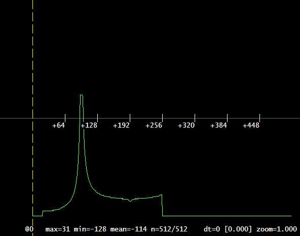
Here is the plot of the response versus frequency using "losamples":
In general, if the optimal frequency that desired, more turns are needed while, conversely, removing turns will raise the optimal frequency. It is good practice to start with more turns that should be needed since removing turns is easier than adding turns since this will usually require soldering on additional leaving a joint within the coil to potentially wear through the enamel on nearby turns causing a short.
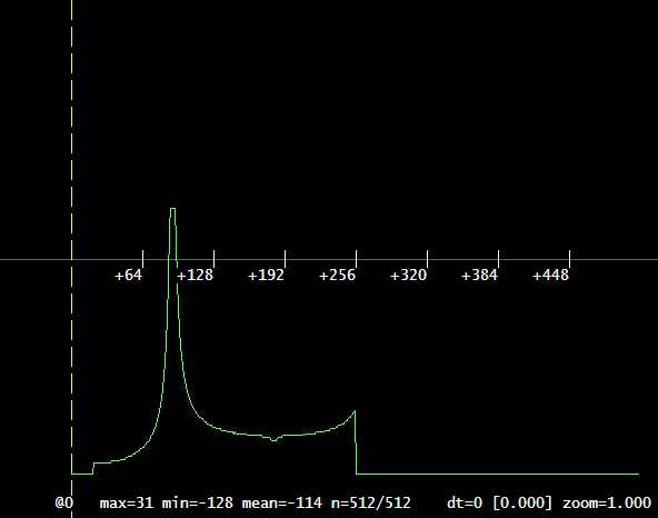
After packaging the antenna and retesting it, I got the following:
> tune

#db# Measuring antenna characteristics, please wait.


# LF antenna: 40.95 V @ 125.00 kHz

# LF antenna: 16.38 V @ 134.00 kHz

# LF optimal: 40.95 V @ 121.21 kHz

# HF antenna: 0.03 V @ 13.56 MHz

# Your HF antenna is unusable.