(Last Mod: 27 November 2010 21:37:20 )
The information contained on this page is the result of work performed, in part, at the Academy Center for Information Security at the United States Air Force Academy. It also forms part of the author's (William L. Bahn) Ph.D./E.E. dissertation work at the University of Colorado, Colorado Springs.
The work detailed here represents the continuing refinement and implementation of theories, concepts, and applications presented in the 14 February 2007 USAF Academy Technical Report (USAFA-TR-2007-01) available from the USAF Academy Public Affairs Office. This research has been funded, in part, by the United States Air Force Information Operations Center (AFIOC), formerly the U.S. Air Force Information Warfare Center (AFIWC), Lackland AFB, TX.
This page contains no classified information and has been approved for public release with unlimited distribution by the U.S. Govt. Public Affairs Office.
This is not a government website and no endorsements of any kind should be inferred.
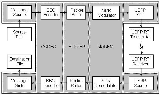
To demonstrate and evaluate a more practical application of BBC-based concurrent codes, a quasi-real-time processing engine has been implemented. This application implements a simple (read: crude) file transfer protocol using a BBC-encoded data channel. The signal flow is shown in the following diagram. The BBC Real-time Engine consists of those blocks on a shaded background.
To perform a file transfer, the following steps are performed:
On the sending machine:
The source data file is renamed usrp_ftp.txf and placed in the same directory as the usrp_ftp.exe file.
The usrp_tx.exe program is run.
The usrp_tx.py program is run (and allowed to run until after the data has been captured by the receiver).
On the receiving machine.
The usrp_rx_cfile.py program is run long enough to capture at least two full packets.
The usrp_rx program is run.
The resulting usrp_ftp.rxf file is renamed to the desired file name.
Since this application is meant primarily to prove the suitability of the real-time codec and modem code, the source and sink modules are very crude. In order to separate file access and transfer time from the performance measurements, the source data is copied completely into memory before the engine starts the timer and the engine places all output data in memory and stops the timer before dumping all of the data to disk at the very end. This places file and USRP data size constraints on the engine that depend on the amount of available memory. It also means that, for large files, there can be significant processing overhead at the beginning or end of the operation.
The next step in the development of the BBC project is to produce GNU radio modules for the modem functions and then build such modules for the codec functions.
One of the most dominant factors on receiver performance is the mark density of the data stream it must process. In general, the lower the mark density the greater the jam resistance but, like all spread spectrum systems, the lower the data rate. Hence the system must strive to balance the tradeoff between jam resistance and data rate by controlling the mark density. Part of the goal of this implementation is to make the evaluation of various tradeoff points fairly easy, which means having fairly easy ways of controlling the stream mark density.
For very low mark densities, the nominal mark density due solely to a single transmitter can be estimated to a good degree by assuming that every mark generated by the encoder results in a distinct mark in the transmitted packet. This, in turn, can be calculated by determining the length of the padded message (and adding two for the bookend marks) and dividing by the length of the packet. If there are multiple messages in a packet, then this number must be multiplied by the load factor. If N is the total number of marks generated by the encoder and C is the number of bits in the packet, then an upper bound on the packet mark density is given by
packet mark density upper limit = N/C
Taking into account that some of the encoder's marks will be degenerate and assuming a random codebook (which BBC is a very close approximation to after the first dozen bits or so) then the expected packet mark density is given by.
expected packet mark density = 1 - [1 - (1/C)]N
A very good approximation to this is given by
expected packet mark density = (N/C) - 0.5*(N/C)2 + 0.15*(N/C)3
and, in fact, the cubic term can be safely ignored (for most purposes) for mark densities below about 50%.
In addition to controlling the mark density within each packet, the overall stream mark density can be increased by transmitting packets such that they partially overlap. To parameterize this effect, the transmitter begins a new packet transmission, on average, after lambda packet lengths have elapsed since the beginning of the previous packet. If lambda is exactly one, then packets are transmitted one after another without overlap but also without any space between them. Lambdas less than one indicate that packets overlap while lambdas greater than one indicate that packets are disjoint in time with space between them.
While a lambda greater than one reduces the mark density of the overall data stream, it has no effect on the mark density of the individual packets. None-the-less, such lambda may be useful depending on the jamming strategy used by the adversary or may even necessary if the decoder needs more than one packet's transmission time, on average, to process each message-bearing packet.
A lambda less than one increases the mark density of each packet by effectively increasing the number of marks placed within the scope of the packet.

The number of marks within the scope of each packet is given by
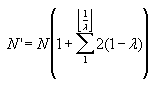
In closed form, this reduces to
![]()
where
![]()
As an example, consider packets formed from 512 bit messages using an expansion of 100, with 1 clamp bit per message bit, 8 random bits added to the beginning of the message, and 100 stop bits added to the end. Including the bookend marks, such a message will have 1142 marks placed within a packet that is 51,200 bits long. The upper limit on the mark density for such a packet is 2.23%. Using the cubic equation above, the expected mark density would be 2.21% and using the exponential equation it would also be 2.21%. If a lambda of 0.12 were chosen, then K would be the floor of 1/0.12 which is 8. The number of marks would therefore by multiplied by a factor of 8.36 to 9547 marks per packet period. This results in an upper limit of 18.6% and an expected density of 17.0%.
For "back-of-the-envelope" estimates, it can be noted that simply dividing the upper limit density by the lambda produces a conservative yet very useable estimate of the packet density. In the example above this estimate yields 18.6%.
It should be kept in mind that the above discussion deals with the mark densities as generated at the transmitter. In addition to the fact that the receiver may be working with the combined data streams from multiple transmitters, there is also the fact that the receiver's demodulator may produce multiple marks for each one that is transmitted. In general it should probably be assumed that the receiver will produce an additional mark per group of marks (i.e., one or more adjacent marks) in the data stream as part of compensating for oscillator skew and jitter.
The USRP program is configured via an ASCII text file containing keyword/value pairs. The file is processed as follows:
Each line is independent of all others.
Leading whitespace on any line is ignored.
Comments lines are those that are empty, contain only whitespace, or whose first non-whitespace character is '#' (a pound sign).
Keywords are case insensitive.
Keywords and values are separated by whitespace, colons, equal signs or any combination consisting of at least one of these.
String values must be enclosed in double quotes and consist of everything between the first pair of such quotes.
The following keywords are presently recognized.
| Keyword | Default | Type | TX | RX |
| DIAGNOSTICS | 1 (ON) | INT | X | X |
| SCHEDULER_TX_NOTRX | 1 (TX) | INT | X | X |
| SCHEDULER_REALTIME | 0 (Virtual Time) | INT | X | X |
| SOURCE_NAME | "usrp.txd" (TX); "usrp.srp" (RX) | STRING | X | X |
| CODEC_MESSAGE_BITS | 512 | INT | X | X |
| CODEC_RANDOM_BITS | 8 | INT | X | X |
| CODEC_CLAMP_BITS | 1 | INT | X | X |
| CODEC_FRAGMENT_BITS | 1 | INT | X | X |
| CODEC_STOP_BITS | 50 | INT | X | X |
| CODEC_EXPANSION | 100 | INT | X | X |
| CODEC_PACKET_LOAD | 5 | INT | X | |
| CODEC_DECODE_LIMIT | 10 | INT | X | |
| BUFFER_PACKETS | 2 | FP | X | X |
| BUFFER_LAMBDA | 1 | FP | X | |
| MODEM_PACKET_RATE_BPS | 500000 | INT | X | X |
| MODEM_SAMPLES_PER_BIT | 4 | INT | X | X |
| MODEM_GAIN_DB | 80 | FP | X | X |
| MODEM_CHANNEL_LOSS_DB | 3 | FP | X | |
| MODEM_THRESHOLD_PCT | 46 | FP | X | |
| MODEM_HYSTERESIS_PCT | 5 | FP | X | |
| MODEM_JITTER_BITS | 1 | FP | X | |
| MODEM_CUSHION_PCT | 1 | FP | X | |
| SINK_NAME | "usrp.srp" (TX); "usrp.rxd" (RX) | STRING | X | X |
| SINK_SAMPLE_LIMIT | 1000 (RX) | INT | X |
Discussion of each parameter is contained in the discussion of the principle block that depends on it.
The message format for this simple-minded file transfer protocol is as follows:
[Checksum] [StreamID] [SeqNum] [DataBits] [Data]
StreamID: This is 16-bit integer that identifies the data stream (essentially identifying the sender and hence a gentleman's proxy for a digital signature).
Checksum: This is a 32-bit checksum value of everything in the message (after the checksum). At the present time, it is hard-coded to all zeros for simplicity in the initial implementation.
SeqNum: This is a 16-bit integer sequence number starting with 0 and incrementing by one for each subsequent message.
DataBits: This is a 16-bit integer that indicates the number of actual data bits contained in the Data field.
Data: This is the actual data payload. It is a fixed-length block, but the actual number of data bits may be less than the block length, particularly for the message containing the last bits of the file or if the message length is not an integral number of bytes. Any unused bits in the message may contain random values.
Note that the message source code does not go to the effort to make use of every single message bit. The amount of data that is placed in each message is always an integral number of bytes and any fractional byte will be unused and may contain random bit values. This is not any kind of fundamental requirement and future versions may use all available bits. It was simply easier to implement this way.
The first message (sequence number zero) is a header message whose payload is the name of the file. The last message contains zero data. The reception of this message serves as a flag to the receiver that the entire file has been transmitted.
NOTE: This section documents the new runtime scheduler that has not been fully implemented yet.
During initialization, the source, codec, modem, and sink modules are created. In addition, the purpose-built buffer that interfaces between the codec and the modem is created. A set of FIFOs are then created. In general, each module has in input FIFO and an output FIFO; the exceptions are the source module, which only has an output FIFO, and the sink module, which only has in input FIFO. Each module is bound to the input and output FIFO that will service its needs. As a result, each FIFO is bound to two different modules, one as the input FIFO and the other as the output FIFO.
The top level runtime scheduler simply calls the source, codec, modem, and sink in a round robin fashion until it senses that the sink's output file is closed. The calls to the individual modules can occur in any order since the modules block themselves unless they determine that there is sufficient data in their input FIFO and sufficient room in their output FIFO to perform their designed task.
Each FIFO contains an "active" flag that is initially HI. This flag tells the module that it feeds into that there is still data forthcoming, even though there might not be any at the present time. When a module senses that its input FIFO is inactive it continues processing any data remaining in the FIFO, pushes any final data into the output FIFO, and then deactivates its output FIFO. Under normal operation this will result in a cascading de-assertion of active flags as the final data works its way through the processing chain.
Each time a module is called, it first checks to see if there is room in its output FIFO for any data it might produce and, if there isn't, it returns immediately without doing anything. If there is, then it checks to see if there is enough data in the input FIFO to produce that data. If there is, then it pops data from the input FIFO, uses it to produce some output data, and pushes that data into the output FIFO. If there isn't, then it checks to see if the input FIFO is still active and, if it is, then it returns without doing anything. If it isn't, then the module performs any cleanup tasks it needs to do deactivates its output FIFO.
The source module is very simple and generic and there is no difference between the source module used in the transmitter and that used in the receiver. Each time the source module is called, it first checks to see if the file it is supposed to read data from is open. If it isn't, then it deactivates its output FIFO and returns. If it is, then it checks to see if there is enough room in the output FIFO to transfer another block of data from the input file. If there isn't, it returns immediately. If there is, it then reads a block of data from the file into its internal buffer, checks how much data was actually read, and pushes that data to the output FIFO. If at least one byte of data was read from the file, the module then returns. Otherwise, if no data was actually read, it assumes that the end of the file has been reached and closes the file; the next call to the module will then result in the output FIFO being deactivated.
The sink module is also very simple and generic and there is no difference between the sink module used in the transmitter and that used in the receiver. Each time the sink module is called, it first checks to see if the file it is supposed to write data to is open. If it isn't then it returns. If it is, then it checks to see if there is enough data in the input FIFO to permit writing an entire block of data to the output file. If there is, then that much data is popped from the input FIFO into an internal buffer and then written to the file. If there isn't, then the module checks to see if the input FIFO is still active. If it is, then the module returns without transferring anything. If it isn't, the module pops whatever data is in the input FIFO into its buffer, writes that data to the file, and then closes the file.
The codec module is, by far, the most complex module in the system. During instantiation it is configured as either an encoder (TX) or a decoder (RX). The encoder draws just enough data from the input FIFO to produce a single message, formats the message according to the ftp protocol, and encodes the resulting message into the packet buffer.
The source module maintains an output FIFO containing either messages to be BBC encoded (TX) or raw USRP data (RX). Each time it is called it checks to see if it has room for another block of data in its input buffer and, if so, reads another block of data from the input file. It then processes as much data in its input buffer as possible by pushing as many items into its output FIFO as it can. Messages are pushed as completely formatted BBC-FTP messages while USRP data is pushed in chunks corresponding to one complete time sample.
The codec module either pops messages from the source and encoded them into the packet buffer (TX) or decoded packets in the packet buffer and pushes any resulting messages into the sink (RX). It only performs its task if it determines that there is both available input data and room for its output data, otherwise it simply returns.
The modem module either pops packet bytes from the packet buffer and pushes raw USRP data into the sink (TX) or pops raw USRP data from the source and pushed demodulated packet bytes into the packet buffer (TX). It only performs its task if it determines that there is both available input data and room for its output data, otherwise it simply returns.
The sink module maintains an input FIFO containing either raw USRP data (TX) or messages that have been BBC decoded (RX). Each time it is called it pops as many items as possible from the input FIFO as it can placing the resulting data into its output buffer. It then checks to see if its output buffer contains enough data to perform a write operation to the output file.
Note that the packet buffer module is not explicitly called by the scheduler. This is because the packet buffer is always the interface between the codec and the modem and both modules maintain their respective portions of the packet buffer's parameters.
NOTE: This section documents the new interblock FIFO that has not been fully implemented yet.
The interblock FIFO is a self-contained data structure with a set of user utility functions that manage it. It is a compromise between a fully insulated object and a directly accessible real-time structure.
The following functions are used to work with the FIFO.
Note: DWORD is typedef'ed to be a 32 bit unsigned integer. On some systems this may be available as type UINT32.
typedef struct
DTS_FIFO DTS_FIFO;
struct DTS_FIFO
{
void *buffer;
DWORD size;
DWORD read;
DWORD write;
DWORD contents_bytes;
DWORD read_size_bytes;
DWORD write_size_bytes;
DWORD buffer_mask;
DWORD overflows;
DWORD underflows;
};
DTS_FIFO *FIFO_New(DWORD
size, DWORD
push_size, DWORD pop_size); // Sizes in
bytes
DTS_FIFO *FIFO_Del(DTS_FIFO
*fifo);
void
FIFO_Push(DTS_FIFO *fifo, void *data);
// Copies push_size bytes from data
void
FIFO_Pop(DTS_FIFO *fifo, void *data);
// Copies pop_size bytes to data
DWORD
FIFO_Size(DTS_FIFO *fifo);
DWORD
FIFO_Contents(DTS_FIFO *fifo);
// Returns the number of bytes of data
DWORD
FIFO_Overflows(DTS_FIFO *fifo);
// Returns the number read items lost
DWORD
FIFO_Underflows(DTS_FIFO *fifo);
// Returns the number write items bypassed
DWORD
FIFO_PushBytes(DTS_FIFO *fifo);
DWORD
FIFO_PopBytes(DTS_FIFO *fifo);
void
*FIFO_Erase(DTS_FIFO *fifo);
//
Zeros pop_size bytes at read pointer
void
*FIFO_Flush(DTS_FIFO *fifo);
// Zeros entire buffer and resets pointers
void
*FIFO_Write(DTS_FIFO *fifo
, DWORD
offset);
// Offset in "push-sized" items (not bytes)
void
*FIFO_Read(DTS_FIFO *fifo,
DWORD
offset);
// Offset in "pop-sized" items (not bytes)
void
FIFO_FilePush(DTS_FIFO *fifo, FILE *fp);
// Copies push_size bytes from file
void
FIFO_FilePop(DTS_FIFO *fifo, FILE *fp);
// Copies pop_size bytes to file
A FIFO overflow occurs with data is pushed to the FIFO even though there is no room for the new data. Since the user has the ability to detect this condition and avoid it, the FIFO Push functions will assume that the user wants the new data pushed into the FIFO at the expense of old data. Accordingly, data at the read pointer will be erased and the read pointer advanced far enough to accommodate the new data. The overflow counter will be advanced once for each read item lost.
A FIFO underflow occurs with data is popped from and empty FIFO. Since the user has the ability to detect this condition and avoid it, the FIFO Pop functions will assume that the user wants continue reading data beyond the present write pointer. Accordingly, NULL data is pushed into the FIFO until the write pointer is advanced far enough to permit the read operation. Since pushing NULL data has no effect on the data already at the write pointer, theoretically no data lost in this process; however, the integrity of data that spans multiple push items might be compromised. The underflow counter will be advanced once for each write item bypassed.
In the interest of runtime efficiency, the FIFO utility functions make certain assumptions about how the FIFO will be used and make no effort to protect the user from misuse.
1) The size of the FIFO is expected to be an integer power of two.
2) The size of items pushed into the FIFO are expected to be the same and an integer power of two.
3) The size of items popped from the FIFO are expected to be the same and an integer power of two.
The reason for the above restrictions is to permit the FIFO to assume that the end of the buffer (i.e., the point where it must wrap around) will not occur in the middle of an item being pushed into or popped from the FIFO. To enforce this policy, the FIFO_New() function increases the size of each of these quantities to the next higher integer power of two if necessary.
To minimize the number of times that data must be transferred, the FIFO gives the user access to the present read and write pointers allowing the user to directly transfer data into or out of the FIFO. It is very important that the user do so only in increments equal to the number of push or pop bytes, as appropriate, that the FIFO was configured for.
To allow the user to work with data in place that may not lie exactly at the read and write pointers, the FIFO can be asked to compute and return a pointer to a data item that is offset from the present read or write pointers. It is very important that the user not do this directly since, in general, they will not know where the end of the FIFO's buffer is.
To get a better understanding of the FIFO block and its functions, let's look at an example program where we want to place values of one type into the FIFO and pop them out as values of a different type to see what happens when data is improperly typed. For example, if we push values of type double into the FIFO, then each time we push a value we place eight bytes of data into the FIFO. If we pop them as values of type float, then each pop only removes four bytes from the FIFO and we must pop two items for each item we push.
The BBC transmitter, at the highest level, is a very simple construct. First the transmitter invokes a configuration manager to determine the user's choices for a variety of options. Then the transmitter's source, codec, buffer, modem, and sink modules are instantiated. Finally, a runtime scheduler is launched that ping-pongs control back and forth between the codec and the modem until it detects that both the source has no more data and that the modem has processed all of the data that has been received from the codec.
What follows is a brief discussion of the runtime scheduler followed by a high level description of the runtime scheduler and then fairly detailed discussions of the modules that make up the actual signal flow chain.
SCHEDULER_TX_notRX: {0 = Receiver, 1 = Transmitter}Default: 0
This flag tells the runtime engine whether to configure the modules and the scheduler as a transmitter (if true) or a receiver (if false).
SCHEDULER_REALTIME: {0 = Data driven, 1 = Time driven) Default: 0
This flag tells the scheduler whether to use actual processor time in making its control decisions or whether to ignore time and make control decisions only on the availability of data. The data driven model will never result in lost data and can give an indication of the performance limits of the code while the time driven model can reveal transient performance limitations that can result in lost data.
The scheduler ping-pongs back and forth between the codec (encoder) and the modem (modulator). Normally, the scheduler runs until it detects two things: (1) that the source has no more data to be transmitted and (2) that all of the data thus far has been encoded, modulated, and sent to the sink. It will also terminate abnormally any time it detects that the sink cannot accommodate any more data.
The scheduler gives priority to the modem since it must keep pace with the transmitter's appetite for data; hence the modem will be invoked any time the transmitter's input buffer has room for the additional data associated with a byte of packet data. Each time it is invoked, the modem will produce the number of USRP data samples corresponding to one byte of packet data. If the buffer has a byte of packet data awaiting transmission, that packet byte is popped from the buffer. If the buffer does not contain any available data, then dummy (zero-valued) samples are generated corresponding to a fictitious packet byte and the buffer is left untouched.
The scheduler invokes the codec only if (a) the transmitter's needs are presently satisfied, (b) a message from the data source is available, and (c) the buffer contains sufficient room to hold the packet that will result. Each time it is invoked, the codec will encode a single packet and place it in the buffer. This is an atomic operation in the sense that all of the other modules can assume that, once called, the encoder will run to completion before relinquishing control. Thus no other block need ever worry about partial packets being in the buffer that are still being encoded.
The source file can be of any type, however due to the large amounts of USRP sample data that can result (and that must be held in memory) it is best if the file size is kept to no more than a few kilobytes.
SOURCE_NAME: {"file name"} Default: "usrp_ftp.txd" (for TX)
This parameter holds the name of the source data file, including its extension (if any). The file must reside in the present working directory.
The source block reads the data from the source file and breaks it into a series of BBC messages. Each message contains four fields organized as follows:
[Checksum] [StreamID] [SeqNum] [DataBits] [Data]
StreamID: This is 16-bit integer that identifies the data stream (essentially identifying the sender and hence a gentleman's proxy for a digital signature).
Checksum: This is a 32-bit checksum value of everything in the message (after the checksum). At the present time, it is hard-coded to all zeros for simplicity in the initial implementation.
SeqNum: This is a 16-bit integer sequence number starting with 0 and incrementing by one for each subsequent message.
DataBits: This is a 16-bit integer that indicates the number of actual data bits contained in the Data field.
Data: This is the actual data. It is a fixed-length block, but the actual number of data bits may be less than the block length, particularly for the message containing the last bits of the file or if the message length is not an integral number of bytes. Any unused bits in the message may contain random values.
Note that the message source code does not go to the effort to make use of every single message bit. The amount of data that is placed in each message is always an integral number of bytes and any fractional byte will be unused and may contain random bit values. This is not any kind of fundamental requirement and future versions may use all available bits. It was simply easier to implement this way.
The last message containing actual data is followed by a message containing zero data. The reception of this message serves as a flag to the receiver that the entire file has been transmitted.
CODEC_MESSAGE_BITS: {Number of bits in the message being encoded.} Default: 512
CODEC_RANDOM_BITS: {Number of random-valued bits to prepend to the message.} Default: 0
CODEC_CLAMP_BITS: {Number of checksum bits to prepend to each message fragment.} Default: 1
CODEC_FRAGMENT_BITS: {Number of bits in each message fragment.} Default: 1
CODEC_STOP_BITS: {Number of checksum bits to append to the message.} Default: 100
CODEC_PACKET_EXPANSION: {Size of the encoded packet as a multiple of message length.} Default: 100
CODEC_PACKET_LOAD: {Number of messages to be encoded into each packet.} Default: 10
All of the values, except for the packet expansion factor, are intrinsically non-negative integers. Even though there is no fundamental reason for the packet expansion factor to be an integer, it is also so constrained (purely for implementation convenience).
The BBC encoder takes each message, encodes it into a BBC packet, and places the packet in the buffer for the Modulator to retrieve. In practice, the packet is encoded in-place within the buffer. The encoder neither knows nor cares anything about the internal structure of the message; it simply sees a message as a string of bits that is to be BBC-encoded.
The best way to visualize the encoding process is to embrace the concept of the "padded message" which is constructed using the following algorithm:
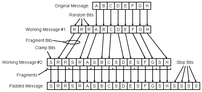
NOTE: In this example, the encoder has been configured for 8 message bits, 3 random bits, 1 clamp bit, 2 fragment bits, and 4 stop bits
Construct the first working message by prepending the indicated number of random bits to the message.
Construct the second working message as follows:
WHILE: Any bits remain in the first working message
Append the indicated number of clamp bits to the second working message.
Move as many bits as possible, up to the indicated number of fragment bits, from the front of the first working message to the end of the second working message.
Construct the final padded message by appending the indicated number of stop bits to the second working message.
With a little planning, the bits of the padded message can be constructed on demand and the actual padded message need never be stored.
The packet is generated with the following algorithm:
Initialize a packet, containing all spaces (LOs), of a length determined by the number of message bits and the message expansion factor.
Place "bookend marks" in the packet by setting the first and last packet bits HI.
FOR: Each message indicated by the packet load
Construct the padded message as indicated previously.
FOR: Each prefix of the padded message.
Compute the hash of the message prefix.
Convert the hash to a packet bit location.
Place a mark in the packet at that location by setting the indicated bit HI.
It should be noted that this implementation is not the most efficient, only arguably the conceptually-simplest iterative design. It is certainly possible to construct an implementation that only works directly with message bits since the random and checksum bits can be dealt with in place very easily. This is the way that the recursive encoder in the BBC Research Engine works and it is likely that similar features will eventually be added to iterative real-time engine's encoder.
BUFFER_PACKETS: {Number of packets that can be held in the buffer.} Default: 4.0
BUFFER_LAMBDA: {Fraction of a packet length the write pointer is to advance after each packet is encoded.} Default: 1.0
The buffer is essentially a FIFO with a couple of application-specific tracking parameters.
In hardware, the FIFO could be implemented as a chain of shift registers (although this is not too commonly done for other reasons) since all of the registers can be shifted concurrently on a single clock cycle. For a FIFO constructed in computer RAM, this is very inefficient. Instead, the FIFO is constructed as a circular buffer in RAM by wrapping the read and write pointer back to the beginning of the buffer's address space anytime they attempt to advance past the end. To make this wrapping efficient, the FIFO's size is forced to be an integral power of two so that a simple masking out of the appropriate higher order bits will perform the desired wrapping operation.
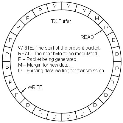
The buffer controller maintains the following status information:
write: The index of the start of the next packet to be written.
read: The index of the next packet byte to be modulated.
data_count: The number of packet bytes ready for transmission.
margin: the number of buffer bytes beyond what is needed for a new packet.
Upon creation, the read and write pointers both point to the same location, data_count is initialized to zero, and margin is initialized to the size of the buffer minus the number of buffer bytes needed for a packet. Each time the modulator reads a byte of packet data from the read location the read index is incremented while the data_count value is decremented and the margin is incremented. Each time the encoder finishes encoding a packet, the write index is advanced by the number of buffer bytes corresponding approximately to one lambda of a packet while the data_count value is increased and the margin decreased by this same amount. In the strictest since, data_count and margin contain redundant data, however, because of how they are initialized, they can be used more cleanly. Namely, if data_count is zero there is no data in the buffer ready for transmission while if margin is less than zero there is insufficient room in the buffer to store a new packet.
If the parameters are chosen properly so that the encoder and modulator can keep pace, the buffer should never attempt to overrun or underrun. However, the behavior of the buffer if either of these events should occur is important and should at least be understood, if not designed so as to be benign. A buffer overrun would occur if more data is written to the buffer than there is free space in the buffer. The consequences of this would be lost data from previously encoded packets. Buffer overruns can be completely eliminated by simply not allowing the encoder start encoding a packet unless there is sufficient room in the buffer to accept the entire packet.
A buffer underrun, on the other hand, occurs if the modulator attempts to pull data from the buffer than it contains. If the buffer's lambda is one or greater this can be made a benign event by simply transmitting null packet bytes until a new packet's worth of data is available. However, if the buffer's lambda is less than one, then it must be assumed that portions of packets that have already begun transmission lie beyond the current write pointer. One way to deal with this would be to retreat the read pointer by one full packet so that any partial packets are replayed. Another way to deal with the situation is to continue pulling data from the buffer and pushing the write pointer ahead as needed. The effect of doing this is simply to delay the starting point for the the next packet to be encoded, which is a benign factor. Thus the transmitter should never lose data provided the modulator can keep pace with the transmitter's appetite.
Clearly the buffer must be able to hold at least one complete packet, however it is not at all obvious that a buffer this size will actually function. In point of fact it will (in theory). When this occurs, the initial value of margin will be zero, which will allow packet data to be stored. Once the packet data is stored, the write pointer will be advanced the by the amount determined by the buffer's lambda (which must be no greater than one in this situation) resulting in a negative margin. The encoder will therefore not place any more packet data into the buffer until enough of the prior packet's data has been transmitted. It is highly likely that the buffer will underrun which will simply push the write pointer further than desired resulting in an increase in the effective lambda.
MODEM_PACKET_BIT_RATE: {The transmission rate for packet bits} Default: 500000
MODEM_SAMPLES_PER_PACKET_BIT: {The number of USRP samples per packet bit} Default: 4
MODEM_GAIN_DB: {The nominal signal level of a mark} Default: 80.0
The modulator is (embarrasingly) simple. It is a direct baseband modulator that takes one byte of packet data and, for each of the eight bits contained, multiplies the bit's value (0 for a space and 1 for a mark) by the modem gain, converts the result to a quadrature IQ sample pair formatted as IEEE-754 single-precision floating point values, and pushes one pair of values to the USRP sink for each sample covered by a single packet bit. As simple as this description is, the reality is even simpler. Each IQ sample pair is either <gain, 0> for a mark or <0, 0> for a space. The configured modem gain is in decibels but, at configuration time, is converted to a linear signal gain and stored as a directly accessible constant.
The maximum value for the USRP data is 32767 (with -32768 on the other extreme). This corresponds to a modem gain of 90.3 dB. A gain of 80 dB results in a signal value of 10000 units, which is convenient.
A number of efficiency enhancements could be made to the modulator. For instance, there is no real need for the modulator to generate or store Q data since it is always zero. This is done purely to make a direct binary dump from memory to the file simpler. Of course, if this is not desired, then there is no driving need to convert and store the values to floating point within the modulator.
Even if it is desired for the modulator to produce the exact data that the sink expects, it is possible to increase processing efficiency at the expense of memory efficiency by constructing a look-up table (LUT) at configuration time. Since the packet data is processed a byte at a time, the table would have 256 rows with a column for each bit in the byte. If only the I samples are stored (in IEEE format), then the entire table would require only 8KB of memory. This strategy could be used to craft arbitrary IQ waveforms, albeit at the expense of even more memory. For instance, at 16 USRP samples per packet bit, a complete arbitrary IQ data LUT would require 256KB of RAM. This is not an unreasonable LUT requirement for many, if not most, platforms.
SINK_NAME: {"file name"} Default: "usrp.src" (for TX)
SINK_LIMIT: {Maximum number of packets-worth of samples to allocate.} Default: 1000
SINK_CUSHION_PCT: {Percentage of a packet's worth of samples to prepend/append to final data stream} Default: 1.0
The sink module is nothing more than a large block of memory that is allocated at configuration time to hold a maximum number of USRP sample pairs. When the data is eventually dumped to the disk file, a run of quiet samples is both prepended and appended to the data. This cushion is to allow for any artifacts introduced by the hardware at the beginning and end of transmissions, although to data the USRP hardware seems capable of wrapping around to the beginning of a data file without such artifacts. It is not known if the initial transmission contains any leading artifacts, however it is believed that any such artifacts would likely only result in additional packet marks and would not suppress any.
The sink module emulates an input buffer that represents the number of samples that have been fed to the transmitter that have not actually been transmitted yet. This is purely for the purpose of scheduling and has (at present) no actual affect on the flow of data. The status of this buffer is maintained by the scheduler.
The actual transmitter used is the USRP with a Flex400 daughter board installed. The Gnu Radio code is extremely simple in that it reads complex IQ data from a file (the one written by the real-time engine) and broadcasts that data continuously until manually terminated. The code is a minor modification of the usrp_siggen.py example Python program that comes with Gnu Radio.
The BBC receiver, at the highest level, is a very simple construct. First the receiver invokes a configuration manager to determine the user's choices for a variety of options. Then the receiver's source, modem, buffer, codec, and sink modules are instantiated. Finally, a runtime scheduler is launched that ping-pongs control back and forth between the codec and the modem until it detects that both the source has no more data and that the codec has processed all of the data that has been received.
What follows is a brief discussion of the configuration manager followed by an high level description of the runtime scheduler and then fairly detailed discussions of the modules that make up the actual signal flow chain.
SCHEDULER_TX_notRX: {0 = Receiver, 1 = Transmitter}Default: 1
This flag tells the runtime engine whether to configure the modules and the scheduler as a transmitter (if true) or a receiver (if false).
SCHEDULER_REALTIME: {0 = Data driven, 1 = Time driven) Default: 0
This flag tells the scheduler whether to use actual processor time in making its control decisions or whether to ignore time and make control decisions only on the availability of data. The data driven model will never result in lost data and can give an indication of the performance limits of the code while the time driven model can reveal transient performance limitations that can result in lost data.
The scheduler ping-pongs back and forth between the codec (decoder) and the modem (demodulator). Normally, the scheduler runs until it detects two things: (1) that the source has no more data to be received and (2) that all of the data thus far has been demodulated, decoded, and sent to the sink. It will also terminate abnormally any time it detects that the sink cannot accommodate any more data.
The scheduler gives priority to the modem since it must keep pace with the receiver's production of data; hence the modem will be invoked any time the receiver's output buffer has enough data in it build another byte of packet data and the buffer can accommodate the resulting packet byte. Each time it is invoked, the modem will consume the number of USRP data samples corresponding to one byte of packet data and push the resulting byte into the buffer. If the receiver's output buffer is almost full, then new bytes of packet data are generated regardless of whether the packet buffer can accommodate them. If necessary, the oldest byte of data is overwritten and the read pointer pushed ahead resulting in the loss of data.
The scheduler invokes the codec only if (a) the receiver's needs are presently satisfied, (b) a complete packet's worth of data exists in the packet buffer. Each time it is invoked, the codec will decode all of the packets that start anywhere within the byte of packet data located at the read pointer. The packet is decoded in place and is an atomic operation in the sense that all of the other modules can assume that, once called, the decoder will run to completion before relinquishing control. If the packet's mark density is too high, then the decoder can get bogged down extracting an exponentially large number messages from the packet. This is handled by placing an upper limit on the number of messages that the decoder is allowed to extract from a given message before abandoning the decoding effort. In a practical system, this limit should probably be established in real-time by letting the decoder run until the receiver's output buffer is filled to some preset level indicating potential loss of data if the decode is allowed to continue. This permits graceful degradation and automatic recovery of performance.
The actual receiver used is the USRP with a Flex400 daughter board installed. The Gnu Radio code is extremely simple in that it reads complex IQ data from the USRP and dumps it directly to a disk file (the one that will be read by the real-time engine). At the present time the code is simply the usrp_rx_cfile.py code that comes with Gnu Radio and has not been modified. Obviously the receiver needs to capture a complete packet in order to successfully decode it. To be safe, it is best to assume that the recording begins with the second bit in the packet and must run until that packet is broadcast again in its entirety. If the transmitter's data file contains a single packet, then a recording that is slightly more than twice as long as the transmitter's cycle should suffice. If the transmitter's data file includes a number of packets, then a recording that is slightly longer than one pass through the data file plus one additional packet should be adequate. It must be kept in mind that person doing the recording does not know exactly when the actual recording of data started and also that there is a switching transient that significantly corrupts the initial few dozen samples of the recording. There are two solutions to this problem. The first is simply to record long enough to ensure that enough data has been captured, however this can result in excessively huge data files. The second is to examine the length of the transmitter's data file, add enough samples to accommodate one more packet, and then add a few hundred samples for good measure and instruct the USRP to only record the resulting number of samples.
SOURCE_NAME: {"file name"} Default: "usrp.src" (for RX)
This parameter holds the name of the source data file, including its extension (if any). The file must reside in the present working directory.
The source module simply reads the data from the source file and brinks it into main memory as a single chunk.
The source module emulates an output buffer that represents the number of samples that have been fed to it from the receiver that have not actually been processed yet by the demodulator. This is purely for the purpose of scheduling and has (at present) no actual affect on the flow of data. The status of this buffer is maintained by the scheduler.
MODEM_PACKET_BIT_RATE: {The transmission rate for packet bits} Default: 500000
MODEM_SAMPLES_PER_PACKET_BIT: {The number of USRP samples per packet bit} Default: 4
MODEM_GAIN_DB: {The nominal signal level of a mark} Default: 80.0
MODEM_CHANNEL_LOSS_DB: {The assumed loss of signal amplitude due to the channel} Default: 3.0
MODEM_THRESHOLD_PCT: {The discriminator threshold as a percentage of peak expected integrator output} Default: 46.0
MODEM_HYSTERESIS_PCT: {The separation of rising and falling discrimator thresholds as a percentage of peak expected integrator output.} Default: 5.0
MODEM_JITTER: {The number of packet bits to extend a detected mark to allow for random jitter} Default: 2.0
The demodulator pulls enough data from the USRP source to generate the next eight packet bits which are packed into a byte and pushed into the packet buffer.
The demodulator is actually a infinite impulse response radiometric decimating discriminator. Despite the long name, it's operation is actually quite simple. As the data is read in, it is squared and integrated to produce a total energy signal. The integrator also includes an IIR low-pass filter giving it a relatively short memory. The governing difference equation is:
y[n] = ( alpha * y[n-1] ) + ( 1 - alpha )*( v2[n] )
Where y[n] is the integrator output and v[n] is the present signal level. The v[n] value is obtained by taking the Pythagorean sum of the quadrature data pairs yielding
y[n] = ( alpha * y[n-1] ) + ( 1 - alpha )*( i[n] * i[n] + q[n] * q[n] )
In order to streamline the computation, the equation is implemented as follows:
v2[n] = i[n] * i[n] + q[n] * q[n]
y[n] = v2[n] + alpha * ( y[n-1] ) - v2[n] )
The decimating discriminator functions as a three-state finite state machine (FSM) with the following states:
Discriminator is LO
Discriminator is being forced HI by present integrator output.
Discriminator is being held HI by past integrator output.
The discriminator state is updated after each sample and after the number of samples corresponding to a packet bit have gone by the state is used to determine the next packet bit that is recorded. The third state is controls the jitter compensation in that it holds the output of the discriminator HI for a set amount of time after the integrator would otherwise have allowed it to go LO.
BUFFER_PACKETS: {Number of packets that can be held in the buffer.} Default: 4.0
The buffer is essentially a FIFO with a couple of application-specific tracking parameters.
In hardware, the FIFO could be implemented as a chain of shift registers (although this is not too commonly done for other reasons) since all of the registers can be shifted concurrently on a single clock cycle. For a FIFO constructed in computer RAM, this is very inefficient. Instead, the FIFO is constructed as a circular buffer in RAM by wrapping the read and write pointer back to the beginning of the buffer's address space anytime they attempt to advance past the end. To make this wrapping efficient, the FIFO's size is forced to be an integral power of two so that a simple masking out of the appropriate higher order bits will perform the desired wrapping operation.
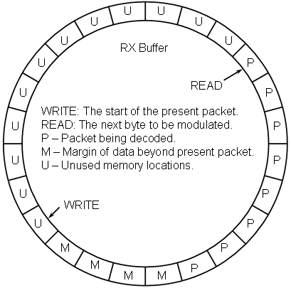
The buffer controller maintains the following status information:
write: The index of the start of the next packet to be written.
read: The index of the next packet byte to be modulated.
margin: The number of packet bytes in buffer beyond the scope of the present packet.
unused: The number of buffer bytes available for new data.
lost_bytes: The number of packet bytes that have been overrun and lost.
Upon creation, the read and write pointers both point to the same location, unused is initialized to the size ofthe buffer and margin is initialized to the negative of the number of buffer bytes needed to store a packet. Each time the demodulator writes a byte of packet data, it first examines if there are any available locations. If there are, it writes the data, advances the write pointer, decrements the unused value, and increments the margin value. If there are not, (unused is equal to zero) then the write pointer is pointing to the same place as the read pointer. In this case, the new data is still written and the write pointer is advanced, but the read pointer is also advanced which means that the margin is unchanged, the number of unused locations remains the same (still zero), and that all eight packets that start within that byte are lost. Hence the lost_bytes counter is incremented.
In contrast, each time the decoder runs (which will only happen if the schedule detects that there is at least one full packet in the buffer, as indicated by the value of margin being non-negative) all packets that start with any of the eight bits in the byte located at the read pointer will be decoded and any messages that result pushed to the message sink. Once finished, the decoder will pop the first byte out of the buffer by advancing the read pointer, decrementing the margin counter, and incrementing the unused counter. In the strictest since, margin and unused contain redundant data, however, because of how they are initialized, they can be used more cleanly. Namely, if unused is zero there is no space for new data in the buffer (without overwriting old, but unprocessed, data) while if margin is less than zero the buffer does not presently contain a full packet's worth of data.
Clearly the buffer must be able to hold at least one complete packet, however it is not at all obvious that a buffer this size will actually function. In point of fact it could, although the likelihood of loosing data is fairly high. Assuming that the pacing is such that no data is lost, what will happen with this minimal buffer size is that the write pointer will initially make one complete circuit until it is once again aligned with the read pointer. At this point unused and margin will both be equal to zero and the decoder can decode a packet, which will free up one byte of buffer space which the modulator can then fill.
CODEC_MESSAGE_BITS: {Number of bits in the message being encoded.} Default: 512
CODEC_RANDOM_BITS: {Number of random-valued bits to prepend to the message.} Default: 0
CODEC_CLAMP_BITS: {Number of checksum bits to prepend to each message fragment.} Default: 1
CODEC_FRAGMENT_BITS: {Number of bits in each message fragment.} Default: 1
CODEC_STOP_BITS: {Number of checksum bits to append to the message.} Default: 100
CODEC_PACKET_EXPANSION: {Size of the encoded packet as a multiple of message length.} Default: 100
CODEC_PACKET_DECODE_LIMIT: {Maximum number of messages to be decoded from a single packet.} Default: 100
All of the values, except for the packet expansion factor, are intrinsically non-negative integers. Even though there is no fundamental reason for the packet expansion factor to be an integer, it is also so constrained (purely for implementation convenience).
The BBC decoder removes a packet from the buffer and extracts all of the messages, up to the allowed limit, that are consistent with that packet. In practice, the packet is decoded in-place within the buffer. It pushes any messages found into the message sink and, when finished, removes the packet from buffer. The decoder neither knows nor cares anything about the internal structure of the messages; it simply sees messages as strings of bits that were BBC-encoded.
The best way to visualize the decoding process is to embrace the concept of the "padded message" which is easiest to describe in terms of the encoding process using the following algorithm:
Construct the first working message by prepending the indicated number of random bits to the message.
Construct the second working message as follows:
WHILE: Any bits remain in the first working message
Append the indicated number of clamp bits to the second working message.
Move as many bits as possible, up to the indicated number of fragment bits, from the front of the first working message to the end of the second working message.
Construct the final padded message by appending the indicated number of stop bits to the second working message.
The goal of the decoder is to first extract padded messages from the packet and then to extract the actual messages from any padded messages that are found. To do this, a depth first search is performed using the following algorithm:
IF: Bookend marks are not found at both ends of the packet
EXIT
Initialize a padded message (so that it is empty).
Append a zero to the padded message.
WHILE: The padded message is not empty.
Compute the hash of the present padded message.
Convert the hash to a packet bit location.
IF: A mark is found at the location.
IF: The padded message is no complete
Add the padded message to the output message queue.
ELSE
Append a zero to the padded message.
CONTINUE (go to Step 4 - the WHILE statement)
Remove all trailing bits back to the last non-checksum zero.
IF: padded message is not empty.
Change the last non-checkum zero to a one.
It should be noted that this implementation is not the most efficient, only arguably the conceptually simplest iterative design. It is certainly possible to construct an implementation that only works directly with message bits (perhaps temporarily treating the random bits as message bits) since the checksum bits never need to be branched on. This is the way that the recursive decoder in the BBC Research Engine works and it is likely that similar features will eventually be added to iterative real-time engine's decoder.
SINK_NAME: {"file name"} Default: "usrp.rxd" (for RX)
SINK_LIMIT: {Maximum number of packets-worth of samples to allocate.} Default: 1000
The sink module is nothing more than a large block of memory that is allocated at configuration time to hold a maximum number of messages. When the data is eventually dumped to the disk file, the messages are scanned for a message having a sequence number of zero. If found and if it has a non-zero number of data bits, the rest of the messages are searched for an unbroken chain of sequence numbers up until a message is found containing zero data bits. If such a chain is found, the data bits are extracted from the messages, in sequence number order, until the entire file is constructed. If such a chain is not found, a report is generated indicating which sequence numbers are missing. If a message having zero data bits is located it will be assumed that this is the last message in the chain and any messages with higher sequence numbers will be reported as probable errors. If a terminal message is not identified, the report will include data for all of the sequence numbers actually received.
Since it is possible that multiple message streams are being sent concurrently, the above process is repeated for each stream ID that is found. So that there is a convenient means of performing certain tests, a stream ID of zero is assumed to be a valid message stream that is being generated by an adversary and that is failing authentication at the decoder level. I practice, such messages would not be sent to the message sink at all, but as an approximation they are sent to the sink and the zero-valued stream ID serves as a simple flag to eliminate them quickly. Keep in mind that this is merely an emulation of decoder-level authentication and that the decoder is presently doing no such authentication. The transmitter is transmitting a stream with an ID of zero specifically to create the situation where the decoder fully decodes the messages but they are essentially unseen by the application-level process.
If all of the packets were received, the destination file should be an exact duplicate of the source file.
The following files make up the BBC FTP demo. Instructions for running the demo are contained in the ID456.txt file.
| Source Code | Header File | Description |
| usrp.zip | WinZIP archive of all the files below. | |
| Makefile | Linux make file for GCC compilation. (Note: Remove the .txt extension from the file) | |
| usrp.c | Top level code for real-time processing engine | |
| bbcftp.c | bbcftp.h | The "application layer" functions (more-or-less) for BBC-based FTP. |
| config.c | config.h | User configuration manager. |
| source.c | source.h | Data source module (TX: file to be transferred; RX: USRP complex data). |
| codec.c | codec.h | BBC codec implementation. |
| buffer.c | buffer.h | Packet buffer that sits between modem and codec. |
| modem.c | modem.h | Modulator/demodulator code for USRP complex data <-> BBC packet data translations. |
| sink.c | sink.h | Data sink module (TX: USRP complex data; RX: transferred file). |
| sha1.c | sha1.h | SHA1 code for performing message prefix hashes. |
| dirtyd.c | dirtyd.h | Assorted utility functions that are commonly used. |
| bytes.c | bytes.h | Type definitions for fixed-width variable types. |
| bbc_tx.py | GNU Radio BBC FTP TX program (modified from usrp_siggen.py) (Note: Remove the .txt extension from the file) | |
| usrp_rx_cfile.py | GNU Radio BBC FTP RX program (unmodified from GNU Radio distro) (Note: Remove the .txt extension from the file) | |
| tx123.ini | Transmitter configuration file to transmit ID123.txt. | |
| tx456.ini | Transmitter configuration file to transmit ID456.txt. | |
| rx.ini | Sample receiver configuration file consistent with above transmitter configurations. | |
| ID123.txt | File containing Gettysburg Address | |
| ID456.txt | README file giving instruction on how to run demo. |