GRAY CODES
(Last Modified: 04 November 2010 06:08:38 PM )
A Gray code is a cyclic sequence of vectors with unit Hamming distance between any two adjacent vectors.
Okay, how about we restate that in Human?
A Gray code is a sequence of vectors - such as binary bit strings - in which only one element in a vector changes in going from one state to the next, including wrapping around from the last vector to the first vector. For instance, the sequence {00,10,11,01} is a Gray code while {00,10,01,11} is not.
A very interesting article on the history and application of Gray codes can be found on Wikipedia.
Gray codes find use in many applications in many fields. In most electronic applications the critical issue is glitch states that occur during transitions from one element of the sequence to the next. For instance, in a four bit binary counter the next state after 0111 would be 1000. But what if the state is sampled between the time that it starts to change and the time it is completely finished changing? Since, in general, the bits will not change simultaneously it must be assumed (unless you have additional information about the circuit implementation) that the bits will change one at a time but in random order. In this particular example, all of the bits are going to eventually change which means that it is possible for us to get any of the sixteen possible states when we sample the output. In some applications this could be disastrous. But, if between any two adjacent states only a single bit changes, then when we sample it we will get only one of two possible results, the state before the transition or the state after the transition. Since we are capturing the state information as it is transitioning from one state to the next, it can be argued that either state value is equally valid.
Imagine the following way to construct an n-bit binary Gray code. Take an (n-1)-bit Gray code and append a copy of it that is reflected about the end of the sequence. What this means is take the last element in the original code, reverse the bits in it, and add it to the end of the sequence. Then take the next to last element in the original code and do the same - reverse the bits and add it to the end of the new sequence. Continue doing this, in order, for every element in the sequence. The result at this point is two half sequences, each of which is a Gray code consisting of all possible vectors of length (n-1). We now want to add an additional bit to each vector in such a way that we are guaranteed the result is an n-bit Gray code. To illustrate this, let's take a given 2-bit binary reflected Gray code and transform it into a 3-bit code. At each step, the new bits are shown in bold.
Let's take a moment and examine the constraints we are working under after reflecting the existing code (step 2) in order to decide what options are available in adding the new bit (step 3):
The overall impact of these constraints is the following rule: We must make the additional vector a 0 for all the vectors in one half and a 1 for all the vectors in the other. The result is therefore an n-bit Gray code since across the entire sequence, including wraparound, each vector differs from both of its adjacent neighbors in only one bit position.
Notice that the constraints still give us some choices at each step. Specifically:
As a result, many possible binary reflected Gray codes can be constructed. However, one particular construction is almost universally used, both because it is the simplest construction and, perhaps more importantly, each member can be generated directly from the corresponding state in a normal binary counter and vice-versa. The following is the algorithm for generating the ubiquitous n-bit binary reflected Gray code:
It's easy to see that this is a very easy construction algorithm, but what about the claim that it can be generated directly from a binary counter. That isn't so obvious and, in fact, we won't even attempt to prove it with any rigor. Instead, we will show that we can generate a gray code directly from a binary counter and then do some hand waving to explain why it turns out to be the same gray code generated by the above algorithm.
The generation of a Gray code sequence from a binary sequence is trivially simple to both understand and implement once a couple simple facts are recognized and brought together.
First, consider what happens when a binary counter advances. This is the same as adding 1 to the present state value and, in doing so, the least significant bit always toggles, but it may or may not generate a carry to the next bit. In general, a given bit in the state value will toggle only if the bit before it generated a carry. Consequently, the first bit that does not generate a carry will prevent not only the next bit from changing state, but all higher bits from changing. Thus we have the property that, between any two states in the counter, we can partition the output into two contiguous groups in which all of the bits in the left partition remain static while all of the bits in the right partition toggle state.
For example:
010011|011111
goes to
010011|100000
Now consider the behavior of a 2-bit XOR gate with inputs A and B and output Y, which has the following truth table:
| A | B | Y |
| 0 | 0 | 0 |
| 0 | 1 | 1 |
| 1 | 0 | 1 |
| 1 | 1 | 0 |
The key to notice is that the output toggles state if and only if exactly one of the inputs changes. If neither input changes or if both inputs change, the output remains static.
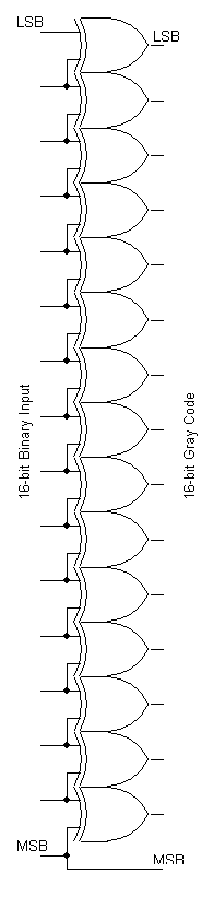
Thus, if we place an XOR gate between each pair of bits in a binary counter's output, the only bit in the vector formed by all of the outputs of the XOR gates that will change when the binary counter is incremented will be the one corresponding to pair of bits that straddles the partition between the static and the toggling portions of the counter output.
This describes a hardware implementation; a software implementation simply involves a bitwise XOR of the binary value and a version of it that has been right shifted by one bit position. In the C programming language, this could be written as:
graycode = binary ^ (binary >> 1);
provided "graycode" and "binary" are both unsigned integer types (and the "unsigned" is important otherwise you invite sign extension which qualifies as "a bad thing").
Notice that there are one fewer XOR gates than there are signals, hence if we just used the outputs of the XOR gates we would have one fewer bits in the output of the converter circuit than in the counter. However, remember that we can prepend as many zeros as we desire to a binary value without changing its value, so let's imagine increasing the size of the counter output by prepending a single bit that is always zero. Note that this happens implicitly when right shifting an unsigned integer to the right in most programming languages. We now feed that static zero into a final XOR gate along with the most significant bit of the counter in order to generate the most significant bit of the converter's output. However, since an XOR gate in which one input is a static zero acts as a non-inverting buffer, we can dispense with the XOR gate and the static zero bit altogether and simply use the most significant bit of the binary counter as the most significant bit of the converter's output. This means that the most significant bit of the gray code value is the same as the most significant bit of the binary value, a fact that will be exploited in recovering the binary value from the gray code value.
It should be noted that if the above converter is going to be used to generate Gray code signals in which the dynamic properties are important, that the output of the converter must be registered since they will be very glitch-prone during the transitions of the binary counter driving it. Thus there will be a one clock cycle latency in the output.
Now to answer the question of whether this algorithm actually produces a Gray code. That it does is a consequence of the fact that between any two adjacent states the only bit in the converter's output that will change is the one corresponding to the left-most bit (in the binary value) that toggled state.
Now, it might seem intuitive that to find the Gray code output corresponding to a particular binary value using this approach that we would have to start with 0 and count until we get to the desired binary value so that the net effect of all of the toggling in the XOR gates as the counter advances can be accumulated. But consider that the converter is a combinatorial circuit having absolutely no memory. Once we count up to the desired value the converter's output is dictated not by the accumulated transitions, but solely by the present value of the counter output. Hence we can convert any arbitrary binary value to the corresponding element of this Gray code using this approach directly.
To show that the resulting Gray code is the ubiquitous binary reflected Gray code described earlier, let's examine the results graphically for a four-bit converter. First, let's examine the output of the binary counter. In the following diagram the lsb is in the bottom row and the msb is in the top row while a white square is a zero and a black square a 1.
| 0 | 1 | 2 | 3 | 4 | 5 | 6 | 7 | 8 | 9 | A | B | C | D | E | F |
The essentially reflective nature of the states is clearly visible, especially if you invert all of the states in either the left half or the right half - and remember that the converter is only sensitive to transitions, so we can invert all of the bits in a given state without affecting the converter's output, provided we are careful to do the same with our fictitious additional bit as well. But instead of playing those kinds of games, let's just generate the resulting converter output and examine it.
| 0 | 1 | 2 | 3 | 4 | 5 | 6 | 7 | 8 | 9 | A | B | C | D | E | F |
Here not only is the reflected nature obvious, but so is the fact the pattern is consistent with the simple algorithm given previously for generating the ubiquitous binary reflected Gray code. Again, this is not offered as a rigorous proof - it is clearly a very hand-wavy argument.
Given a Gray code vector that has been generated from a binary value using the approach described above, we can recover the binary value that generated the Gray code value by exploiting two simple facts:
With this in mind. let's look at how the XOR gates generate the bits in the Gray code value from the binary value from a different perspective. Consider a bit other than the msb (which we already know remains unchanged). It is formed by XOR'ing the corresponding bit in the binary value with the next higher bit. So, if the next higher bit is a zero then the output bit equals the corresponding bit in the binary value but if it is a one then the bit is the complement of the corresponding bit.
Now, what if this same process is applied to the resulting Gray code, namely XOR'ing the corresponding bit in the Gray code value with the next higher bit in the original binary value? Once again, if the next higher bit is a zero then the output bit equals the corresponding bit in the Gray code value, but we already know that, if the next higher bit is zero, that the Gray code bit is equal to the corresponding value in the binary value. Similarly, if the next higher bit is a one, then the output bit is the complement of the corresponding bit in the Gray code value, but we already know that, if the next higher bit is one, that the Gray code bit is equal to the complement of the corresponding bit in the binary value. Since the complement of a complemented value results in the original value, the output is once again equal to the original value of the corresponding bit in the binary value.
The result is that we can retrieve any bit of the original binary value from the corresponding bit of the Gray code value provided we know the value of the next higher bit in the original binary value. Here is where the second fact comes into play. Since the msb of the Gray code value is equal to the msb of the binary value, not only do we already have the msb of the binary value, but we have all of the information we need to generate the next lower bit in the binary value. However, once we have done that, we then have the information needed to generate the next bit down from that. This continues until we reach the lsb and have converted it.
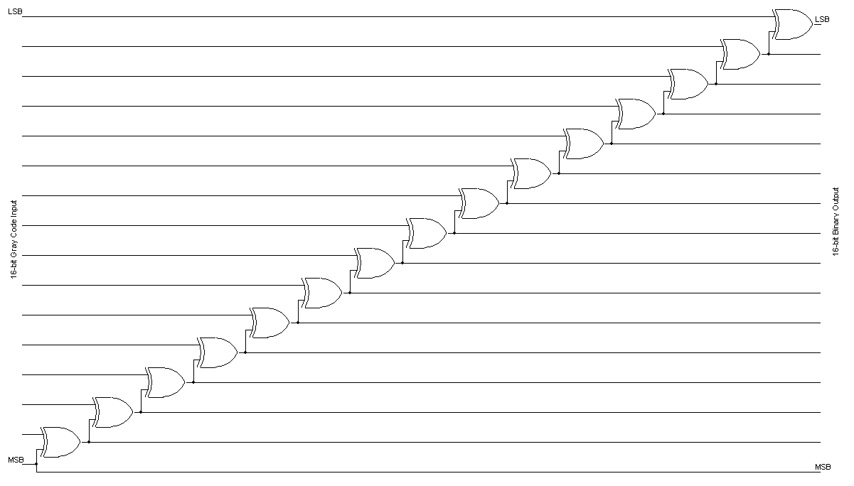
The above approach is very simple and easy to implement, but as can be seen it introduces a long delay path since the conversions must progress serially. However, modern digital circuits are so fast that they can almost always accommodate the long delays. For instance, a twelve bit converter of this type can perform conversions at 50 MHz in a Xilinx Spartan-II part with time to spare. In all fairness, the fact that combinatorial logic is implemented as lookup tables in an FPGA makes this a pretty poor evaluation of the effect of the long delay chain and, even if it were, there would still be many cases where more speed is needed. There are two ways to make the conversions compatible with tighter speed constraints. The first is to pipeline the process which allows the designer to trade throughput for latency. The second is to use another approach altogether that only incurs O(log2(n)) delays instead of O(n) delays.
Before turning our attention to the very efficient and compact standard algorithm, we can get an appreciation for it by noting the fact that each bit in the output of the converter above is simply the parity of the corresponding Gray code bit and all higher Gray code bits. Thus, if we just wanted the least significant Gray code bit, we need a circuit that computes the parity of the entire Gray code value. This can be done in O(log(n)) time by XOR'ing adjacent pairs of bits to get a value that is half as wide and then XOR'ing adjacent pairs of bits in that to get a value that is one-quarter the original width and so on until we have a single bit. This would require four stages and use a total of fifteen XOR gates. Since converting any of the higher bits requires computing the parity of a smaller number of bits, this places an upper bound on the complexity of the overall converter; namely, a 16-bit Gray code value can be converted to binary in O(log(n)) time using no more than 15*16=240 XOR gates. In point of fact, implementing the circuit as sixteen independent parity circuits would require just half that, or 120 XOR gates. In doing so, however, you would hopefully notice that much of the exact same circuitry appears in multiple circuits and could therefore be removed, implemented as a subcircuit, and the output fed to all of the circuits that used it. With a little bit of effort, you could trim the logic from 120 XOR gates to just 49 and have the exact circuit that we develop next.
The key to the standard logarithmic-time algorithm is contained in three key behaviors of the XOR operation:
The first property means that we can re-write an expression like:
(A XOR B) XOR (B XOR C)
with the signals in any order we desire.
In particular, we can re-write it as:
(A XOR C) XOR (B XOR B)
The second property means that the rightmost term is zero
(A XOR C) XOR 0
The third property means that the result can be reduced to:
A XOR B
To make the operations more streamlined, let's temporarily adopt the short hand that AB means A XOR B. With this, we can write the above three steps in a very compact manner:
ABBC => ACBB => AC0 => AC
It's important to note that this is NOT multiplication (in fact, it's modulo-2 addition). The key result is that any time a signal appears twice (not necessarily together) in a purely XOR expression, that pair of occurrences can simply be removed.
For the problem at hand, what this means is that if we have two unknown signals that are XOR'ed together and we wish to separate them, we can XOR the combined signals with another signal that contains one of the two. For instance, in the above case example we were able to separate A from B even without having access to B - in effect, we were able to replace one signal with another (B with C) even though we knew neither.
So now let's track the individual bits as we first convert to Gray code and then back using an 8-bit vector.
| Operation | MSB | LSB | ||||||
| X = Binary | A | B | C | D | E | F | G | H |
| Y = X >> 1 | 0 | A | B | C | D | E | F | G |
| X = Gray = X XOR Y | A | AB | BC | CD | DE | EF | FG | GH |
| Y = X >> 1 | 0 | A | AB | BC | CD | DE | EF | FG |
| X = X XOR Y | A | B | AC | BD | CE | DF | EG | FH |
| Y >> 2 | 0 | 0 | A | B | AC | BD | CE | DF |
| X = X XOR Y | A | B | C | D | AE | BF | CG | DH |
| Y >> 4 | 0 | 0 | 0 | 0 | A | B | C | D |
| X = X XOR Y | A | B | C | D | E | F | G | H |
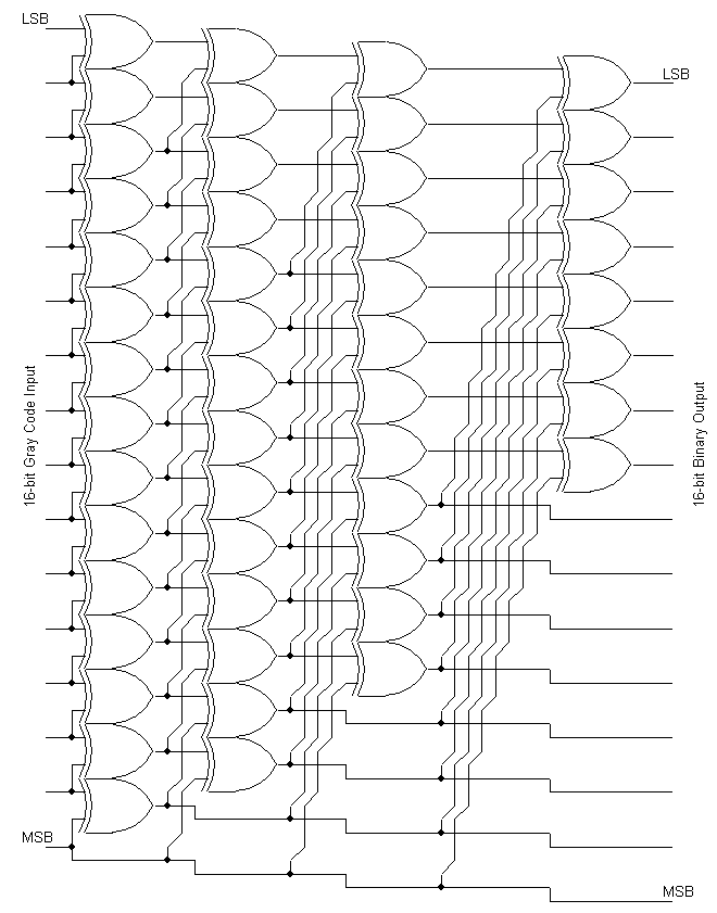
A 16-bit logarithm-time converter is shown below. While it is about four times faster than the linear-time implementation, it comes at the price of requiring nearly four times the silicon area (and hence four times the cost). As with the linear-time circuit, if higher throughput is needed, this design can also be pipelined and, in doing so, can actually cost less to implement than a pipelined linear-time version since the pipeline registers dominate the transistor count.
In C, the above algorithm can be implemented very cleanly:
binary =
graycode;
binary ^=
binary >> 1;
binary ^=
binary >> 2;
binary ^=
binary >> 4;
binary ^=
binary >> 8;
As before, it is important that the variables be of an unsigned integer type (remember - sign extension when bit banging is a bad thing).
Notice that the first stage of the logarithmic-time circuit is identical to the entire binary-to-gray converter schematic shown previously. This means that the above circuit can be used to convert in both directions. If a binary value is applied to the inputs, then the Gray code value can be read by tapping the signals after the first stage while if a Gray code value is applied then the binary value can be read at the final outputs.